6 Pin Power Window Switch Wiring Diagram
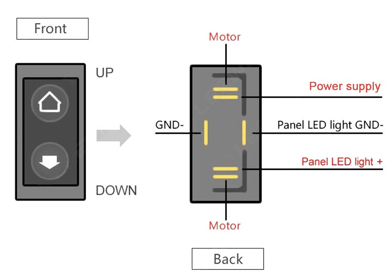
Creating a wiring diagram for a 6-pin power window switch involves understanding the function of each pin. Typically, these switches are used in automotive applications for controlling the movement of the power windows. Here's a basic outline of how a 6-pin power window switch might be wired:
-
12V Power Supply (Input Voltage): One of the pins will be connected to the vehicle's 12V power supply, usually through the fuse box.
-
Ground: Another pin serves as the ground connection.
-
Up Connection to Window Motor: This pin connects to one side of the window motor. When activated, it moves the window up.
-
Down Connection to Window Motor: Another pin connects to the other side of the window motor for the downward movement of the window.
-
Illumination (Optional): In some switches, there might be a pin dedicated to illumination, allowing the switch to be lit up when the vehicle's lights are on.
-
Additional Feature Control or Second Ground: The sixth pin could be used for a variety of purposes, such as an additional feature control (like an auto-up function) or simply as a second ground or power connection, depending on the specific design of the switch.
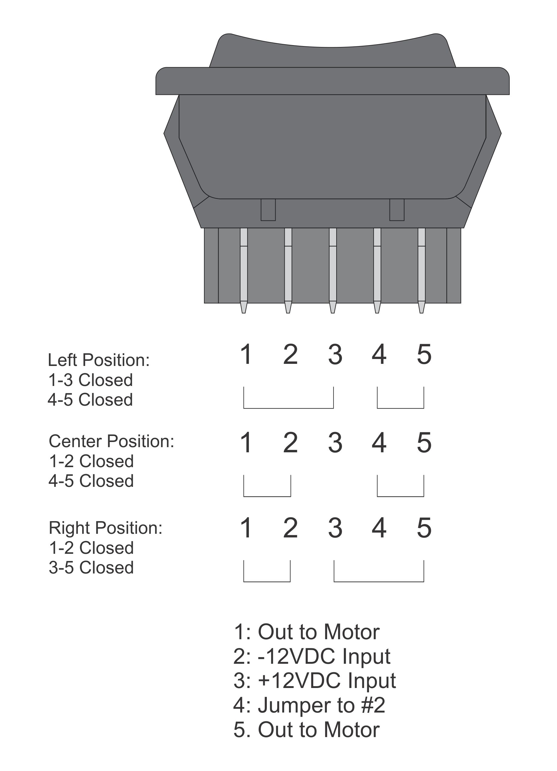
The wiring diagram would roughly look like this:
It's important to note that the exact function of each pin can vary depending on the vehicle make and model and the design of the switch. Always refer to the specific wiring diagram for your vehicle or the switch you are using. If uncertain, consulting a professional or the vehicle's service manual is advised for accurate and safe wiring practices.
