How to wire door lock and power window switches
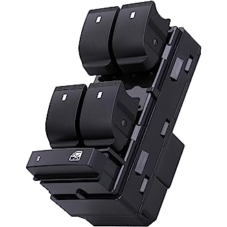
In this video, we're going to wire up some power windows, some door lock switches for the power windows, which is the topic I'm going to tackle. First off, I'm going to show you 2 switches. One here, which is a authentic spell made in USA type window switch with the arrow icons. Also very much popularly known with this little icon, which has a little window icon. This is a 5 wire dual rocker type of switch.
I'm going to explain to you about the wiring, not just for these switches, but almost any switch. Because any of these types of switches, whether it be a window switch, they're all going to have the similar properties, need to be wired the same way. And I'm also going to debunk some of the standardized wiring color codes on both of these switches as well. So here we go.
Now, just so you understand what's going on here on my workbench, I like to show you what I have over there. That's my 12V power supply. Okay? So that red and black pair of wires, which you're going to see every now and then, if you're wondering what they are, that's what they are. These come from my power supply. And I'm going to be using this as my standard 12V supply to do my tutorial with my switch.
Now, over here, this one here is the non spell switch. I know it looks like a real authentic spell made USA real deal. However, unfortunately, this is not. This is the . Now, if you'll notice what the does, and he likes to do an awful lot because he's just so dawncrafty, what is the mimic wire color codes that are USA standards?
Now, on the back of the switch, just so you get a good perspective, front, now, the top and the bottom doesn't really matter because it's just a 5 wire switch. The outer legs, which are the green and the blue, which are also standardized wire colors for aftermarket doylocks, by the way, if it matters to you. Now, the right in the center, that's going to be your positive 12V going into the switch. The 2 Browns, those are going to be both connected to ground, constant ground. Okay?
Now in a typical scenario, this is the way it's going to work. Just sharpen that up real fast just for speed's sake. What I've done is already have this plug partially wired in there on the bottom. The 2 Browns, the ground. So I had this black wire running out and I had this pigtail here for the red, which is going to be my 12V positive. So I'm just gonna ground these 2 blacks. While I'm doing that. I'm gonna hold off on connecting the red just yet and I'll show you why. This switch here you see is non illuminated but when I touch the 12V power. Wait that's not working. What happened by why I came out? This video is getting harder and harder to make. Alright, maybe now it'll work. There's a switch. No lights when I connect. Now you can see that the green lights coming on. Now this is pretty typical and anybody's door panel when you get in your car and you turn your ignition key on, all the switches in your vehicle are going to come on so that way you can find them in the dark, right?
Now here's the trick when you're doing aftermarket switches you have a choice. You can either have the switches wired up on accessory power, constant power, you can get sophisticated and you can even tie them into a delayed door trigger turn off circuit if you wanted to, like a gm vehicle has. A lot of cars have these delayed turn off circuits. Just keep in mind that whenever you have power going to the 12V and you have ground, which you'll always have on the 2 Browns, that's the only time your power windows will work, okay? If your key is off, your power windows aren't gonna work. In some cars, if you have your key in there with the key sense on, that's good enough. The accessory will stay on. It all depends on you.
So whenever you're wiring power window switches, pay good forethought into the your master switch. This one here, let's just say, is your master switch, which is going to control, say, your driver door and also run power to all your other doors for your front passenger, your rears, etc. So on. Make sure that you treat that one right, because whatever you feed into your master switch is also going to be fed in all to all your slave switches. And so many systems can be up to 7 switches in length. So be very careful when you do wire it up. You don't want to do it, see it works, put your door panels all back together just to find out that it's not powered up the exact way that you want it to be. So that's what that's all about.
Now, as far as explaining to you how these things work, why they work, what they do is very simple. And I'm going to explain it to you really fast in a way that you can understand.
Now, this here is my test light. I love this test light because it does a bunch of stuff. It shows me ground and 12V because it's a dual LED. And I can also throw negative and positive voltage from my test light. So with my switch energized, which we know because the LEDs is on in the switch, if I take my test light and touch either one of these output legs from my power window switch. You see that both resting at ground. Now what's going to happen is when you push the switch, to the up position, the up wire is going to throw 12V positive. The other wire is going to be resting at ground. So that, with the opposing polarity in that scenario, is going to make the window go up. When I do testing on the down wire, push the switch in the down position, the opposite is going to happen. So when this one here is throwing troll the 12V positive on here, this one here is getting the opposite 12V negative, and that's what makes the window go up. You reverse the polarity, and it goes down in the other direction. That's how all power windows switches work. It's very simple, straightforward principle. But believe it or not, I get more questions on this than you can even imagine. But that's really all there is to it. It's not that complicated. It's nothing mystical about it whatsoever.
However, when you do have these other types of switches, which could be imports, spell switches, like this one here I want to show you, you can see the pin configuration layout. Much different than what you see on the other one. You got one, 2,3,4,5,6 pins. With these types of switches, it's not always as simple as it is with these types of switches, with this is what I call real standardized wiring, something like this, do yourself a favor, call the manufacturer, know what the pin configurations are, Google it online, ask me or somebody else who knows. So that way you don't screw it up because you don't want to burn your switches up.
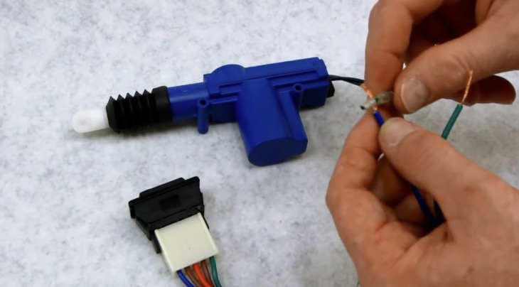
But that is something you should definitely pay good attention to. And while we're on the topic of doing switches, I also want to touch on dollock switches because I've getting, I've gotten questions on this topic as well. So real quick, this here is just a standard 3 pin switch. What's going on here is whatever polarity you put on the center conductor in this case I'm going to be making pretend I'm going to be doing a set of door locks okay, now I'm a fan of safety first for me that's it's the rule and it should be for you so if I have a choice, I would have my door lock system wired up like this where I have ground on my center conductor and I would throw ground on the 2 outer pins for lock and unlock and of course however you mount your switch it's gonna depend on what it is so if you? Want the top to be unlock of course mount the switch in this way if you mounted up this way and you say, oh just reverse the 2 wise. It's not that big of a deal. It's not that serious people but what you're going to see here is ground all the time on the outside.
Just to illustrate, eh, hang on. Actually I can't even do it because my test light isn't connected in circuit but take my word for it. Ground on a center conductor. When I push the switch up here it's going to connect these 2 connectors and it's going to throw ground on, outs on the top, unlock leg down on the lock. That's a wrap. That's all there is to it folks. So door locks if you're going to do it, throw negative signals because the relays, which are going to be mounted elsewhere, gonna be actually doing all the grunt work and throwing all the power. Let those throw the voltage sources around. Don't let the switches do it. It's much simpler, much more effective and better. And that's what we like better. So there you go. There's my tutorial on the switches. See you next time.
